The assignments
Seven-segment driver
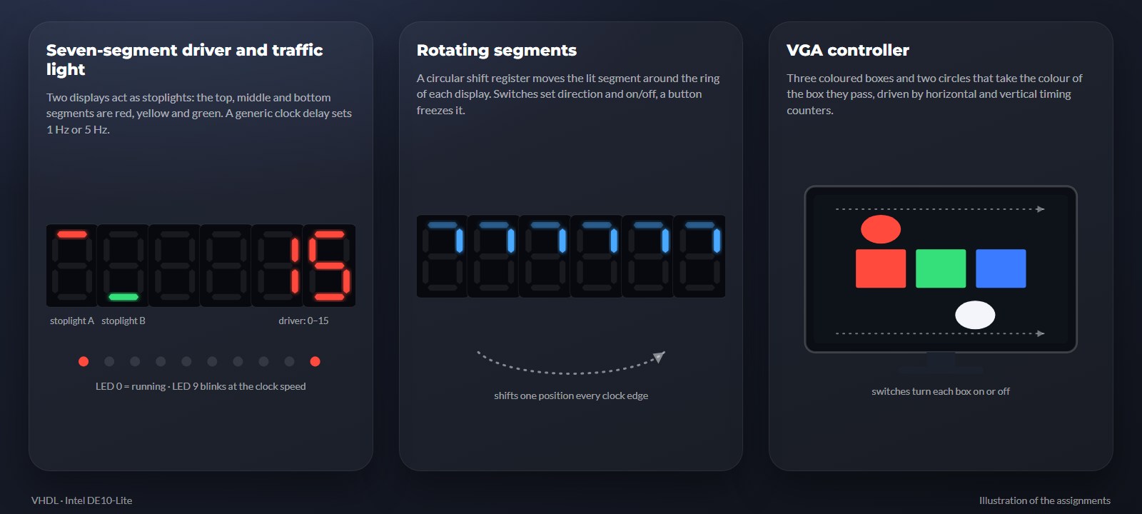
A reusable driver that shows the digits 0–15 on a seven-segment display using a case statement, with two utilities: invert all segments and reverse the bit order. Verified with a waveform simulation in Active-HDL.
Traffic light
A traffic-light intersection on two seven-segment displays, using the three middle segments of each as red, yellow and green. We wrote a generic clock delay (a counter that toggles an output clock) and combined it with the board's PLL to get a 1 Hz normal mode and a 5 Hz test mode, with pause and reset from the switches and buttons. The state machine itself was provided by the course.
Rotating segments
A rotating-light effect on the six displays, built from a demultiplexer, a flip-flop and a generate statement that repeats the stage for every segment, together forming a circular shift register. Switches set the direction and on/off, and a button freezes the pattern.
VGA controller
A VGA controller that draws three coloured boxes and two white circles that sweep across and take the colour of the box they pass. We wrote the horizontal and vertical timing counters and the drawing functions for rectangles and circles, and switches turn each box on and off.
How it's built
- Simulate first, then test on hardware. Every design was first simulated with a testbench in Aldec Active-HDL, then synthesised with Intel Quartus and tested on the DE10-Lite board. The VGA assignment did not require a testbench, so we tested it directly on a monitor.
- Generic and reusable. The clock delay takes the input and desired frequency as generics and counts inClockFreq / (2 × desiredClock) − 1 input cycles before toggling the output, so the same component slows any clock down to what is needed.
- Packages with types and functions. For the VGA assignment we defined types for coordinates, rectangles and circles, and functions that tell whether a pixel lies inside a shape, which keeps the drawing code readable.
- Structure from the course book. The circular shift follows the structure from the book Circuit Design with VHDL, with a generate statement for the repeated stages.
- Defined hardware behaviour. Every assignment has a defined behaviour for the switches, buttons and LEDs, for example pausing with a button and showing the active clock speed on an LED.
Who built what
This was a pair project. The course provided the assignments, the board and a few building blocks (for example the traffic-light state machine and a bit-reverse function); the rest we wrote ourselves.
Tools
Want to know more about this project?
I'm happy to walk you through it.